DXF to G-code converter
Turn a DXF drawing into G-code you can send to a laser or a plotter.
More options
DXF is the everyday exchange format of CAD and cutting machines. Parts designed in Fusion, FreeCAD, LibreCAD or AutoCAD, sheet-metal flat patterns, panels and gaskets, outlines traced in Inkscape: most of them can be saved as DXF. To run one on a GRBL laser, a CNC engraver or a pen plotter without CAM software, you need G-code. This DXF to G-code converter reads lines, arcs, circles, polylines, ellipses and splines, joins them into continuous paths, orders the paths to keep travel short, and writes G-code for a laser or a plotter in millimetres.
How to convert DXF to G-code
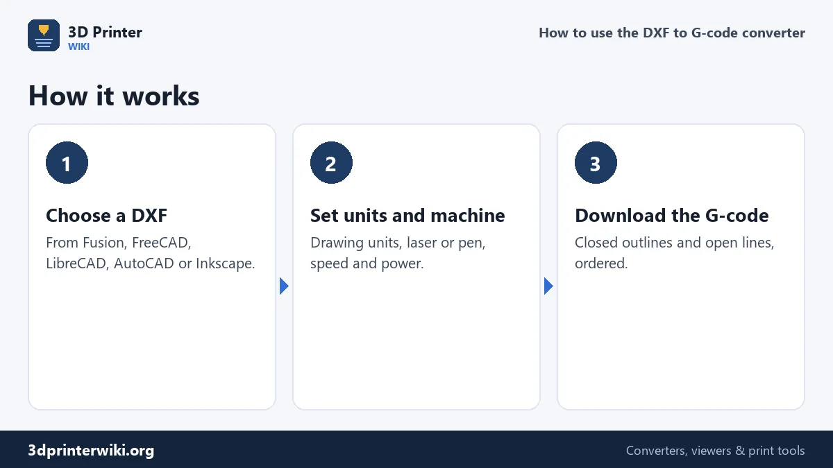
- Choose the DXF on the box.
- Set the drawing units under More options if the size line looks wrong: millimetres, inches or centimetres.
- Set the machine: laser with power and M3/M4 mode, or pen plotter with pen heights; cutting and travel speed; passes.
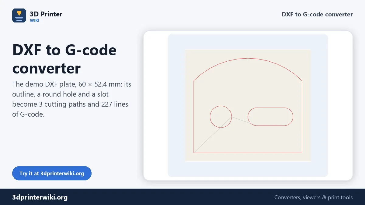
- Check the preview: red lines are cuts, grey lines travel.
- Download the G-code.
What the converter reads
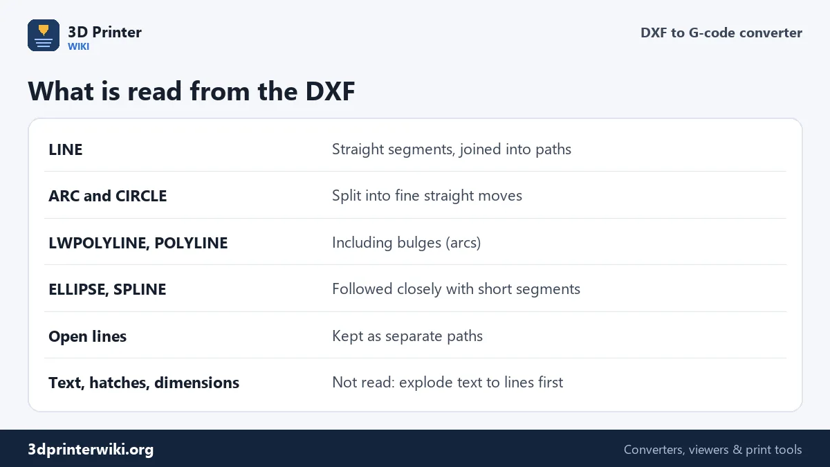
A DXF is a list of entities. LINE entities are single segments, and the converter joins those that meet end to end into continuous paths, so a rectangle drawn as four lines is cut in one go. ARC and CIRCLE entities are split into short straight moves, fine enough to look round at laser speeds. LWPOLYLINE and old-style POLYLINE entities are read with their bulge values, which is how CAD programs store rounded corners in a polyline. ELLIPSE and SPLINE curves are followed with short segments. Closed outlines are cut all the way round; open lines, such as score marks or engraving strokes, are kept as separate paths. Text, hatches, dimensions and blocks are not read, so explode text to lines in CAD and delete dimensions before saving.
The demo plate shows several of these at once: a polyline outline, a circle for a round hole, and a slot drawn from two lines and two arcs, which the converter joins into one closed path. The 60 × 52.4 mm plate becomes three paths, 0.31 m of cutting and 227 lines of G-code.
Units and origin
Many DXF files don't reliably say which unit they use, so choose it under Drawing units: millimetres is the usual choice, inches for drawings from American CAD setups. The size line shows the result, so a part that should be 60 mm and shows 1,524 mm is clearly an inch drawing read as millimetres. The drawing is placed with its bottom-left corner at the machine origin, plus any X and Y offset you set; use Scale to width to resize the whole drawing to a given width.
Cutting order
After each path, the converter picks the nearest path that is left and starts it from its closer end. That keeps travel moves short and saves time. For laser cutting through material, cutting inner holes before the outer outline is good practice, because once the outline is cut the part can shift. The nearest-path order often does that naturally when holes are close to where the machine starts, but check the preview. If the outline is cut first, cut the holes in a separate job, or split the drawing into two DXF files.
Laser and plotter output
For a laser, each path is a travel move with the laser off, M4 or M3 with your S power to switch it on, G1 cutting moves at your feed rate, and M5 to switch it off. For a pen plotter or drag knife, the tool is lifted and lowered with Z moves at the heights you set. The file starts with G21 and G90, millimetres and absolute positions, so it runs the same on any GRBL or Marlin machine.
Working from a 3D model? STL to DXF cuts a profile from it first. For vector drawings, SVG to G-code works the same way, and DXF to STL turns the same drawing into a 3D printed part.
Exporting a clean DXF
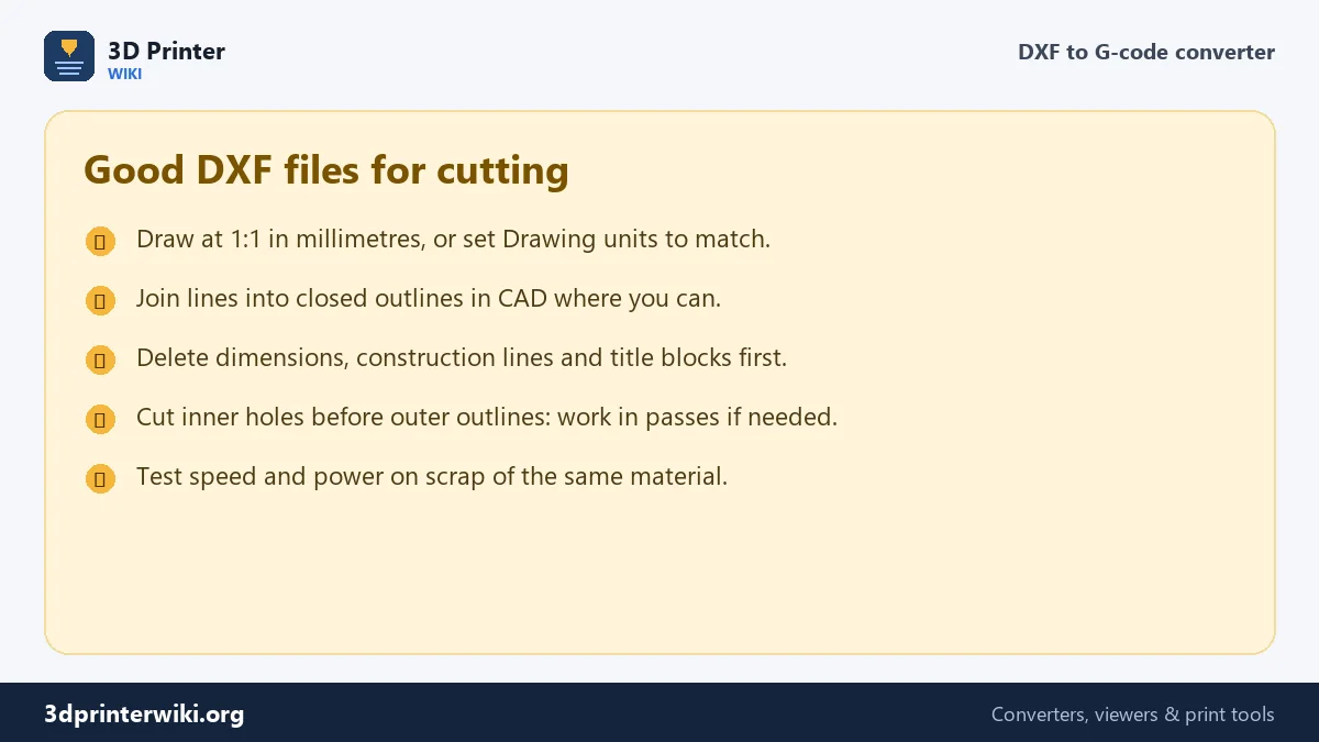
A few minutes of cleanup in CAD saves a lot of trouble at the machine. In Fusion, right-click a sketch and choose Save As DXF, which writes only that sketch's curves. In FreeCAD, select the shapes and use File → Export with the DXF format. In Inkscape, save as Desktop Cutting Plotter (DXF R14) and check that the document units are millimetres. In every program: delete dimensions, centre lines, construction geometry, borders and title blocks, explode text to curves if you want it cut, and make sure parts are drawn at full size. Duplicate lines on top of each other are a common problem: the laser would cut them twice, burning the edge. Most CAD programs have an overkill or delete-duplicates command for that.
DXF to G-code questions
How do I convert a DXF to G-code?
Choose the DXF on this page, set the units and your machine under More options, and press Download G-code.
Which DXF entities are supported?
LINE, ARC, CIRCLE, LWPOLYLINE, POLYLINE, ELLIPSE and SPLINE. Text, hatches and dimensions are ignored.
Why is my part the wrong size?
The drawing uses different units. Set Drawing units to inches or centimetres under More options.
Can I use the G-code on a CNC router?
This tool writes 2D paths for lasers and plotters, without tool offsets or depth passes. For milling, use CAM software that offsets for the cutter.
Does the converter support GRBL?
Yes. It writes standard G0, G1, M3, M4 and M5 moves in millimetres with absolute positions.
Can I cut text from a DXF?
Only if the text has been exploded into lines and curves in CAD. Text entities themselves are ignored.
More 3D printing tools
Updated November 2026 · How these tools work