Gear generator
Design a spur gear, or a pair that meshes, and print it.
The 3MF keeps each gear as its own part.
More options
Gears are one of the most useful things you can print: replacement parts for toys, appliances and machines, reduction drives for robots and models, clock mechanisms, or simply moving parts for a project. A gear only works, though, if its teeth have the right shape. This gear generator makes spur gears with true involute teeth, the profile used by real gears, from the standard values engineers use: tooth count, module and pressure angle. It can make a matching second gear at the correct centre distance, and adds a round or D-shaped bore for your shaft.
How to make a gear
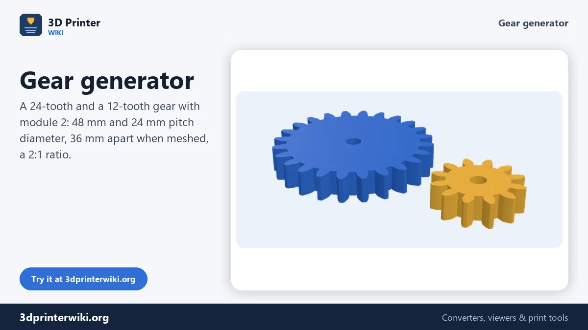
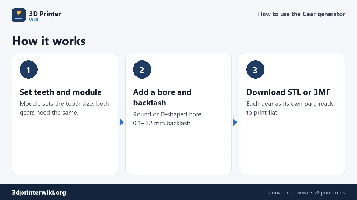
- Enter the number of teeth and the module. Module is the tooth size in millimetres: pitch diameter = module × teeth.
- Add a matching gear by entering its number of teeth, or 0 for a single gear. The status line shows the centre distance and ratio.
- Set thickness, bore and backlash under More options. Tick D-shaped bore for motor shafts with a flat.
- Tick Show the two gears meshed to check how they engage. Untick it again before downloading, so the gears print apart.
- Download the STL, or the 3MF to get each gear as its own part.
Module, teeth and size
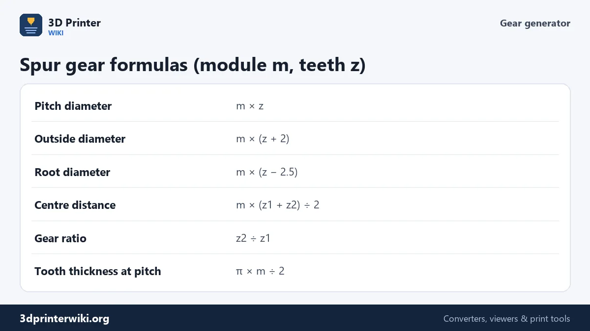
Two gears mesh only if their teeth are the same size, and the module is that size. With module 2, every tooth spaces 2π ≈ 6.28 mm along the pitch circle, whatever the gear's tooth count. The pitch diameter is module × teeth, so a 24-tooth gear with module 2 is 48 mm at the pitch circle and 52 mm across the tips (module × (teeth + 2)). A 12-tooth gear with the same module is 24 mm at the pitch circle, and the two run with their centres 36 mm apart: half the sum of the pitch diameters.
If you are replacing a broken gear, count its teeth and measure the outside diameter. The module is then the outside diameter divided by (teeth + 2). Common modules are 0.5, 0.8, 1, 1.25, 1.5, 2, 2.5 and 3. Old American gears use diametral pitch instead; module = 25.4 ÷ diametral pitch.
Why involute teeth
The curved flank of each tooth is an involute: the curve traced by the end of a string unwound from a circle, the base circle. Involute teeth roll on each other along a straight line of action at a constant angle, the pressure angle, so the gears turn smoothly at a constant speed ratio even if the centre distance is slightly off. That forgiveness is a big advantage for printed gears, where nothing is perfectly accurate. The generator calculates the flanks exactly from the base circle, with a 20° pressure angle by default, the modern standard. 14.5° is an older standard you may need for matching vintage gears.
Backlash and fit
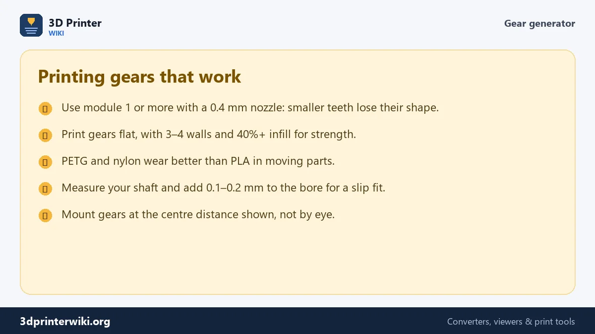
Printed parts come out a little larger than designed, because the plastic spreads. Without any play, printed gears bind. The Backlash setting makes every tooth slightly thinner, by the amount you set measured along the pitch circle, so the gears have room to move. 0.1 to 0.2 mm suits most printers with a 0.4 mm nozzle; increase it if gears feel stiff, decrease it if they rattle. For the bore, measure your shaft and add 0.1 to 0.2 mm for a slip fit, less for a press fit. The D-shaped bore cuts a flat at 10% of the diameter, the usual shape of small motor shafts such as 5 mm stepper shafts.
Printing gears
Print gears flat on the bed, so the teeth are formed by the outlines of every layer and stay accurate. Three or four walls make the teeth solid; 40% infill or more makes the body strong. For gears that run a lot, PETG and nylon wear much better than PLA, which can soften and deform from friction heat. Layer heights of 0.12 to 0.2 mm give smooth flanks. Elephant's foot, the slightly squashed first layer, can make gears bind at the bottom edge; a small chamfer or the slicer's elephant foot compensation fixes it.
Need a box to put the mechanism in? The box generator makes one to measure. For a gear you already have as a mesh, the STL to STEP converter brings it into CAD.
Gear generator questions
How do I make a gear to 3D print?
Enter the number of teeth and the module on this page, set the bore and thickness, and download the STL.
What is a gear module?
The tooth size in millimetres: pitch diameter divided by the number of teeth. Gears only mesh if they have the same module.
How do I calculate the centre distance of two gears?
Module × (teeth of gear 1 + teeth of gear 2) ÷ 2. For module 2 with 24 and 12 teeth, that is 36 mm.
What module is best for 3D printing?
Module 1 or more with a 0.4 mm nozzle. Smaller teeth lose their shape.
How much backlash do printed gears need?
About 0.1 to 0.2 mm on most printers. Increase it if the gears bind.
What is the best material for printed gears?
Nylon and PETG wear better than PLA in gears that run often or carry load.
Can I make a gear for a motor shaft?
Yes. Set the bore to the shaft diameter plus 0.1 to 0.2 mm, and tick D-shaped bore if the shaft has a flat.
More 3D printing tools
Updated November 2026 · How these tools work