IGES to STL converter
Open an IGES or IGS file from older CAD software and save it as an STL.
Same file as: · · · ·
More options
IGES (files ending in .igs or .iges) is one of the oldest CAD exchange formats, and it is still everywhere: in supplier part libraries, old project archives, surface models from Rhino and Alias, and machines that were designed decades ago. Slicers can't read it. This converter opens the IGES file with a real CAD geometry kernel, turns its surfaces into a fine triangle mesh in millimetres, and saves an STL you can print.
How to convert IGES to STL
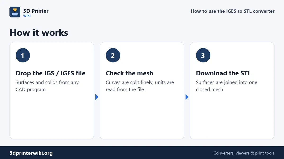
- Drop the .igs or .iges file on the box. The CAD reader (a few megabytes) loads the first time, then the file is read.
- Check the preview. The size is shown in millimetres, whatever unit the file was drawn in. The part count tells you how many separate surfaces or bodies the file has.
- Download the STL. All surfaces go into one STL, where shared edges join up into a closed mesh.
What is in an IGES file
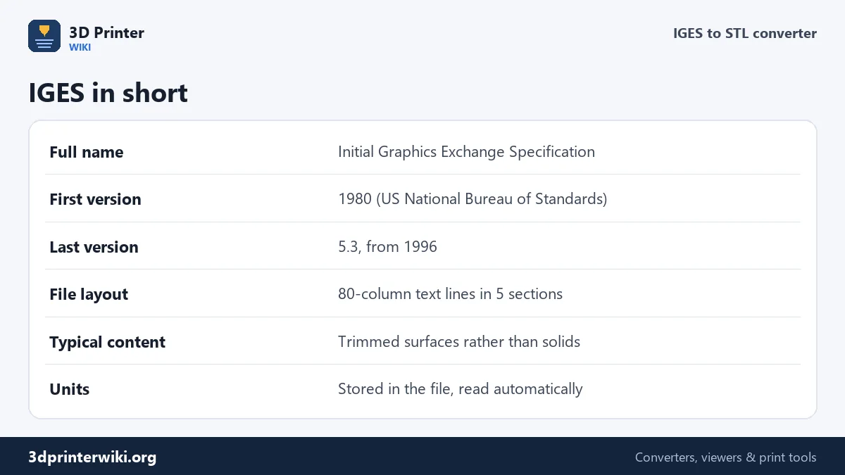
IGES was first published in 1980 by the US National Bureau of Standards, so that CAD systems from different vendors could exchange drawings and models. Its last version, 5.3, dates from 1996. You can open an IGES file in a text editor: it is made of 80-character lines, a leftover from punched cards, in five sections marked S (start), G (global settings such as the unit), D (a directory of every entity), P (the entities' numbers) and T (terminate).
The entities are lines, arcs, splines and surfaces. A 3D part is usually stored as a set of trimmed surfaces: a plane, cylinder or freeform surface plus the boundary curves that cut out the face you see. Solids made of faces that are joined together exist in the standard, but many programs never write them. That's the main difference from STEP, which normally carries a proper closed solid.
Surfaces, gaps and closed meshes
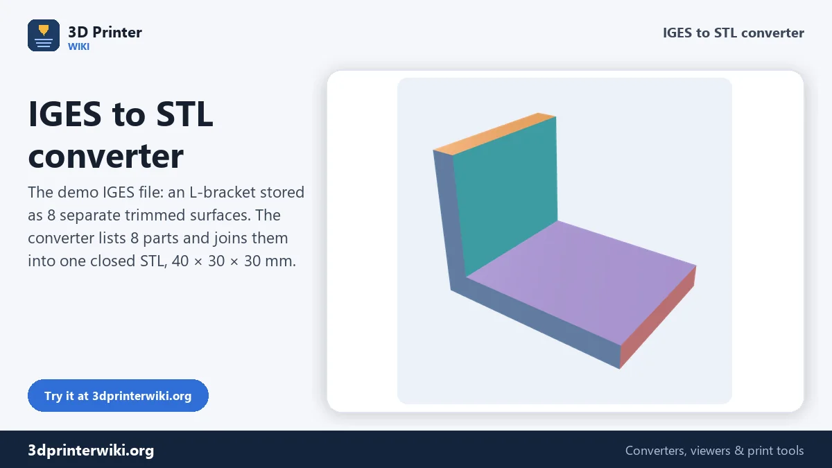
Because an IGES model is often a collection of separate faces, the converter may report many parts, one per surface. That's what the demo file on this page shows: an L-bracket stored as 8 trimmed planar surfaces. Each one is meshed on its own, and when they go into one STL, matching edges are joined. For the demo bracket, the result is a closed mesh with no open edges, 40 × 30 × 30 mm with a volume of 9.75 cm³, exactly as designed.
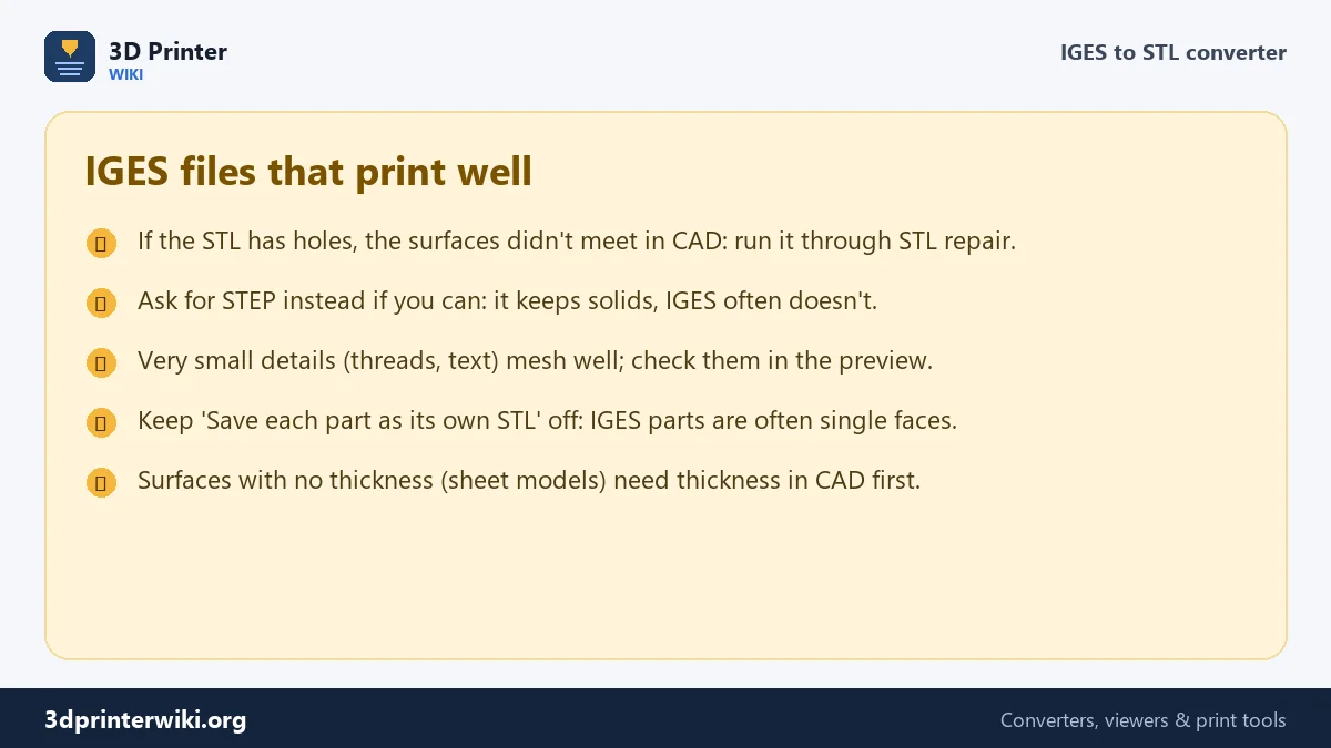
Real files are not always that clean. If the surfaces didn't meet exactly in the original CAD program, small gaps remain, and the slicer may complain about holes or open edges. The STL repair tool joins nearby edges and fills small holes. If whole faces are missing, the file was exported incompletely; ask for it again, ideally as STEP.
Mesh quality
Curved CAD surfaces have to be split into flat triangles. The converter keeps the mesh within 0.05% of the part's overall size of the true surface, so on a 100 mm part, no point is more than about 0.05 mm away from the CAD surface, well below what an FDM printer can show. It also limits the angle between neighbouring facets to about 14°, so every full circle gets at least 25 segments and larger holes and fillets get more. Holes print round, and the STL stays a reasonable size.
Units
An IGES file records its unit in the global section: millimetres, inches, feet, metres and so on. The converter reads it and converts everything to millimetres, so a part drawn in inches shows at its real size. If the file has an unusual or wrong unit setting, check the size shown under the preview, and rescale with the STL scaler if necessary.
IGES or STEP?
If you have the choice, ask for STEP. It is newer (the first STEP standard came in 1994), keeps solids and assemblies together, and is the format almost every CAD program now prefers. For printing, both end up as the same kind of mesh, and the STEP to STL converter uses the same CAD reader as this page. IGES is still the right choice for surface models from Rhino or styling software, and for older systems that don't write STEP.
Exporting IGES for printing
If you are the one exporting the IGES, a few settings help. Export solids or closed surface bodies rather than separate faces when the option exists, and include all bodies you need. Keep the unit set to millimetres. Many programs, including SolidWorks, Fusion, CATIA, Creo and Rhino, can export IGES, and most can also export STEP or STL directly, which is often the simpler path for printing.
IGES to STL questions
How do I convert an IGS file to STL?
Drop the .igs or .iges file on this page, check the preview, and press Download STL.
Is IGS the same as IGES?
Yes. Both extensions are used for the same format.
Why does my IGES file show many parts?
IGES often stores every face as a separate trimmed surface. They are joined into one mesh in the STL.
Why does the STL from my IGES have holes?
The surfaces didn't meet exactly in the original CAD model. Run the STL through STL repair, or ask for a STEP file.
Can I open an IGES file without CAD?
Yes. This page shows it in 3D and gives you the size, and the STEP viewer opens IGES files too.
Can I convert STL to IGES?
Not here. For a CAD file from a mesh, use the STL to STEP converter; nearly every CAD program reads STEP.
Which programs export IGES?
SolidWorks, Fusion, CATIA, Creo, Rhino and most other CAD programs can export IGES files.
More 3D printing tools
Updated November 2026 · How these tools work